
In-House Tooling
In-House Tooling
Built Under One Roof
Every mold we use is machined in our own facility, not outsourced to a separate tool shop. That keeps tooling, molding, and quality under one roof and one point of responsibility.
In-house tooling removes the handoffs that slow a project down. Design changes, tolerance corrections, and trial feedback move directly between our machining floor and our injection lines, which shortens revisions and protects your production timeline. For OEM and ODM buyers, it means the same supplier responsible for your part accuracy also machines the tool that produces it so that we can maintain end to end quality control throughout the process.
We use SLM 3D printing to create custom mold inserts for high-heat areas, incorporating conformal cooling channels to eliminate cosmetic defects and improve final product quality.
5-AXIS MACHINING
HIGH-SPEED CUTTING
SLM 3D PRINTING
CUSTOM MOLD INSERTS
CNC Machining Capacity & Equipment
CNC Machining Capacity & Equipment
Our CNC facility runs eight machining centers built around German and Japanese control systems, including Heidenhain and Siemens from Germany and FANUC and Mitsubishi from Japan. Three of these are 5-axis boring and milling machines, giving us the ability to machine complex mold shapes in fewer setups.
The largest machine handles work up to 3,000 by 2,100 by 1,000mm, so we can cut tooling for large parts in a single setup rather than splitting the work across smaller beds. High-speed machining centers deliver fine surface finishes and detailed geometry work, while our gantry-type machining center supports heavier mold bases. Together this range lets us machine tooling for both small precision components and large structural parts in-house.
8 CNC Machining Centers
3 × 5-Axis / Up to 26,000 RPM
Heidenhain, Siemens, FANUC & Mitsubishi Controls
Measurement & Component Verification
Measurement & Component Verification
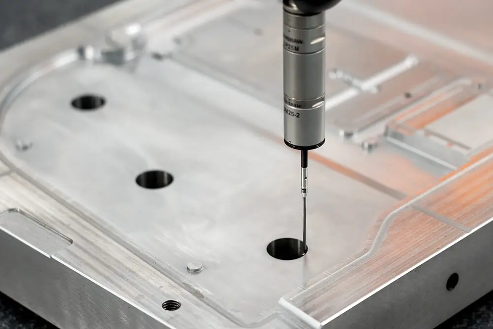
Machined mold components are checked against the original design before they move forward to assembly. We use a Mitutoyo coordinate measuring machine with a 900 by 1,600 by 800mm measuring range to confirm critical dimensions, and a GOM ATOS 3D scanning system that captures full-surface geometry at resolutions down to 1 micron.
This gives us a dimensional record of every machined component against the design, so any deviation is caught and corrected on our floor at the machining stage. It is the same care that runs through the rest of our process: accuracy is proven early, before components are built into a working mold.
Mitutoyo CMM dimensional verification
GOM ATOS 3D scanning to 1 micron resolution
Components proven against design data before assembly
Photos
Tooling Gallery
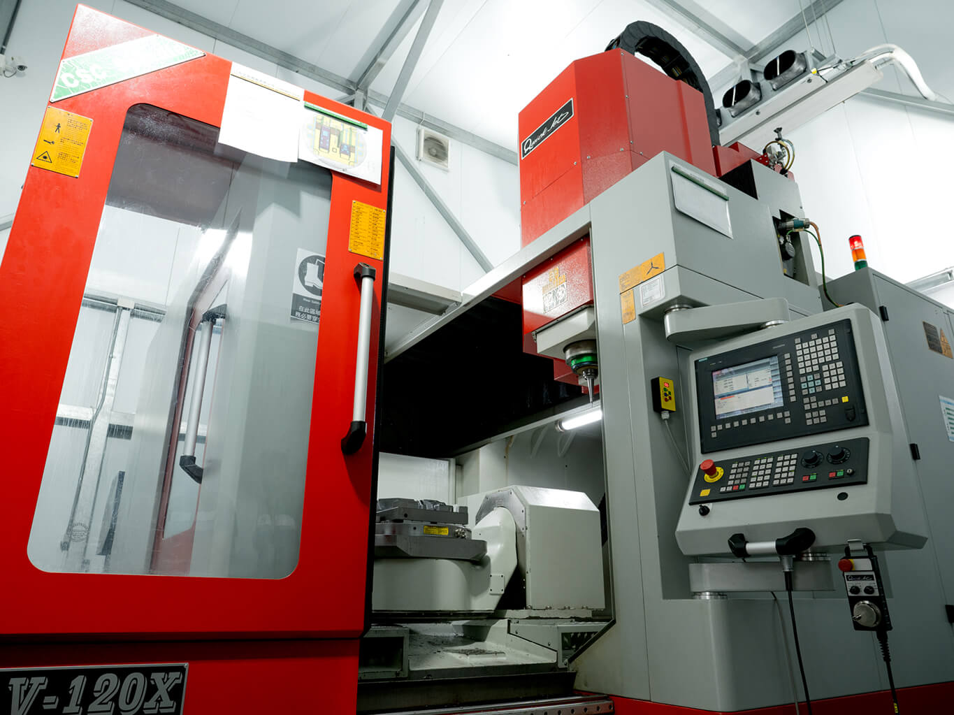
High-speed vertical machining center AMP's Quaser V-120X high-speed vertical machining center housed in a climate-controlled room for precision mold component work
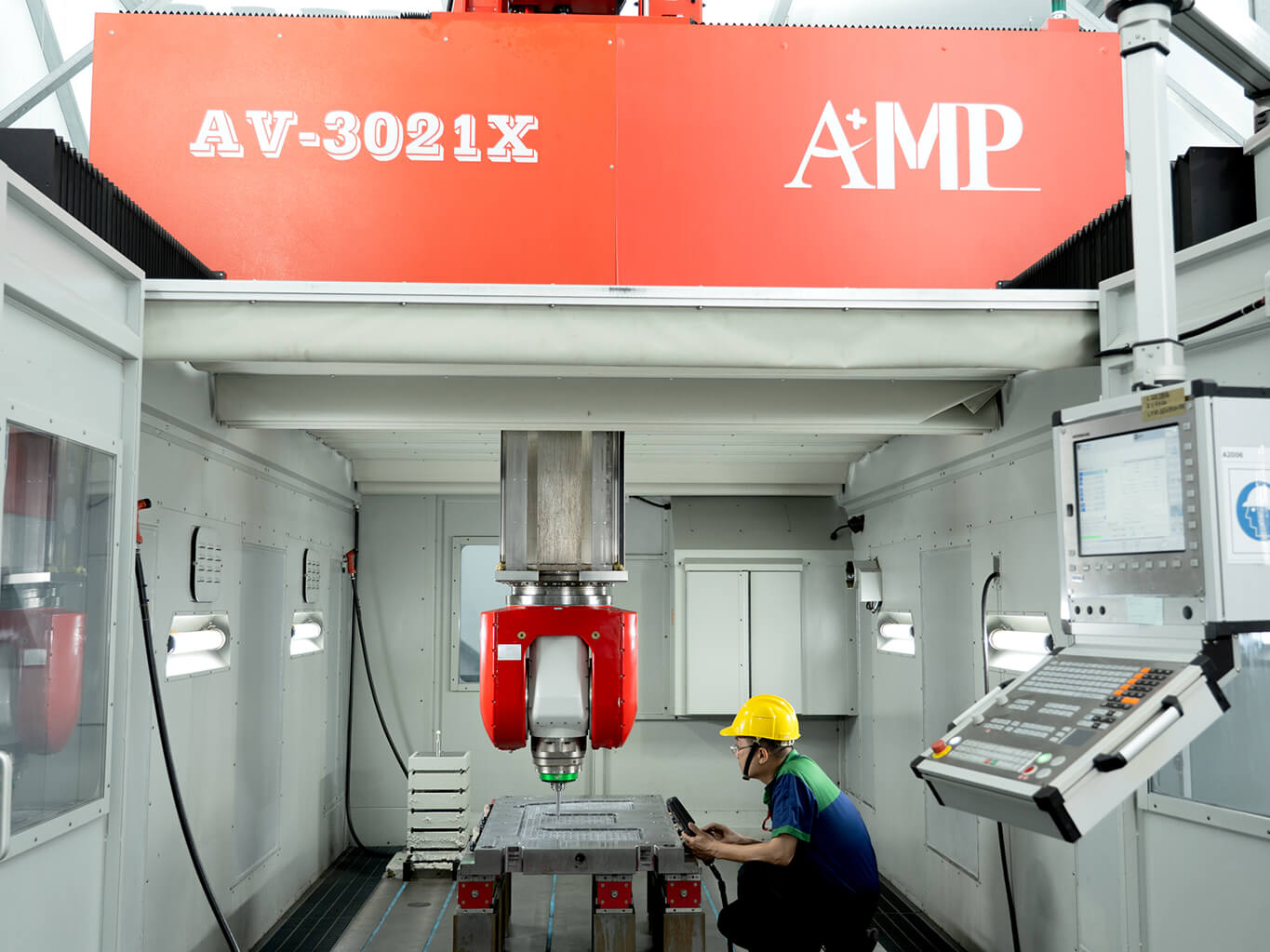
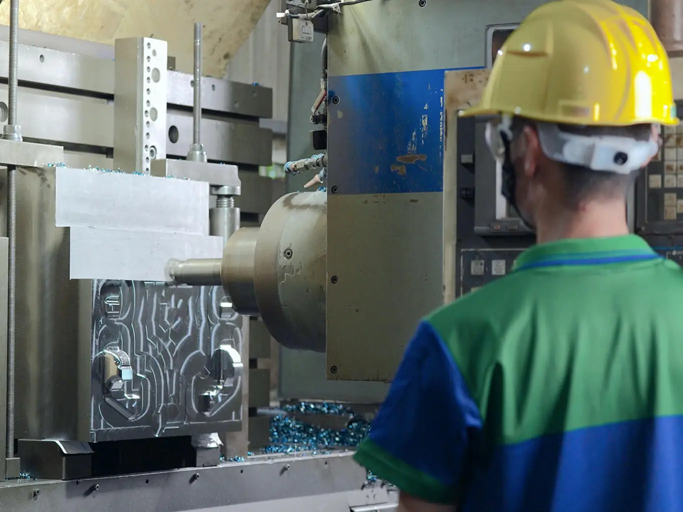
AMP 5-axis gantry machining center AMP's AV-3021X 5-axis gantry machining center with operator setting up a mold base, handling work up to 3,000 × 2,100 × 1,000 mm in a single setup
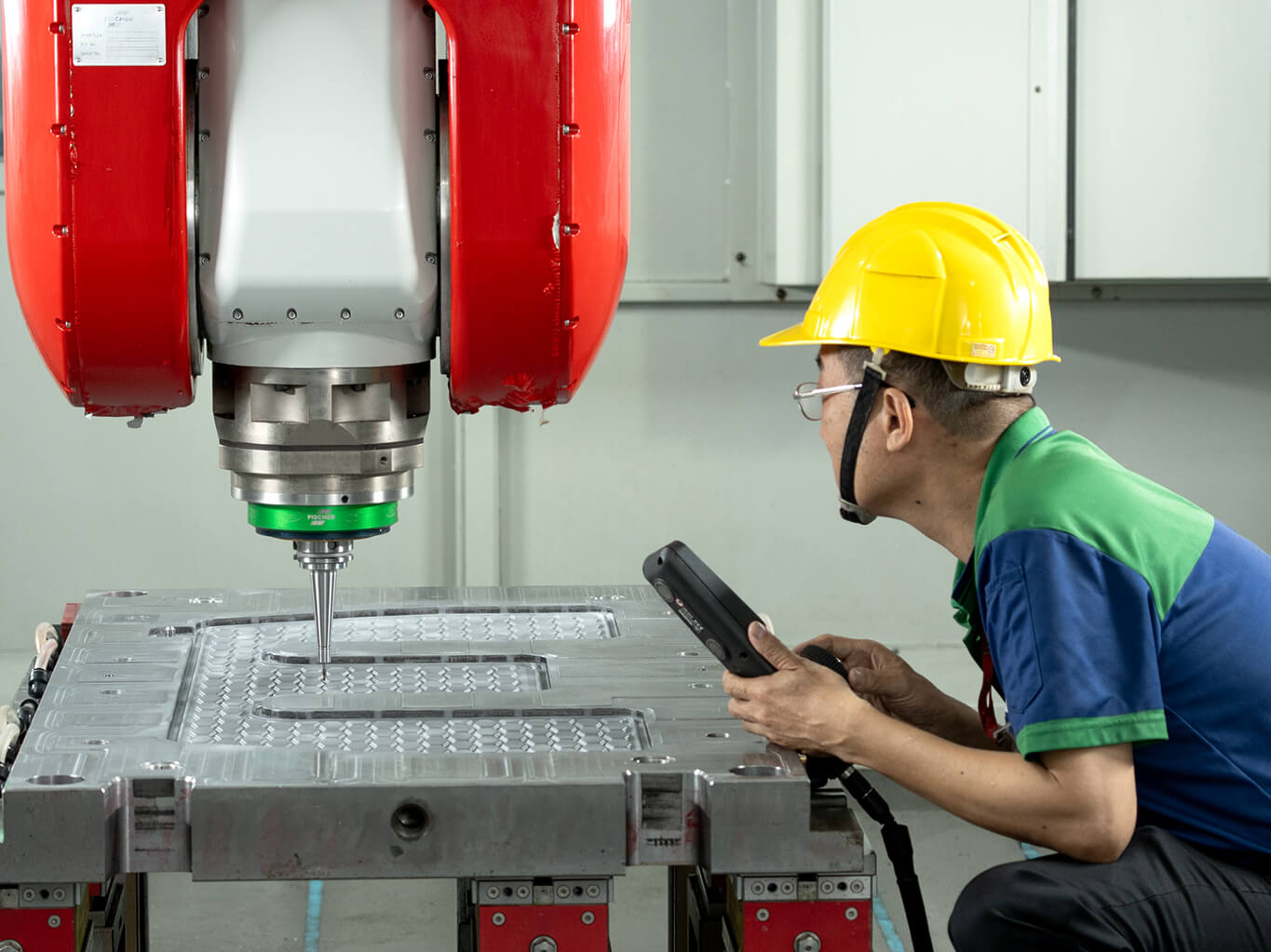
5-axis mold cavity machining AMP operator guiding the 5-axis gantry machining center via handheld pendant while cutting detailed cavity geometry into a mold
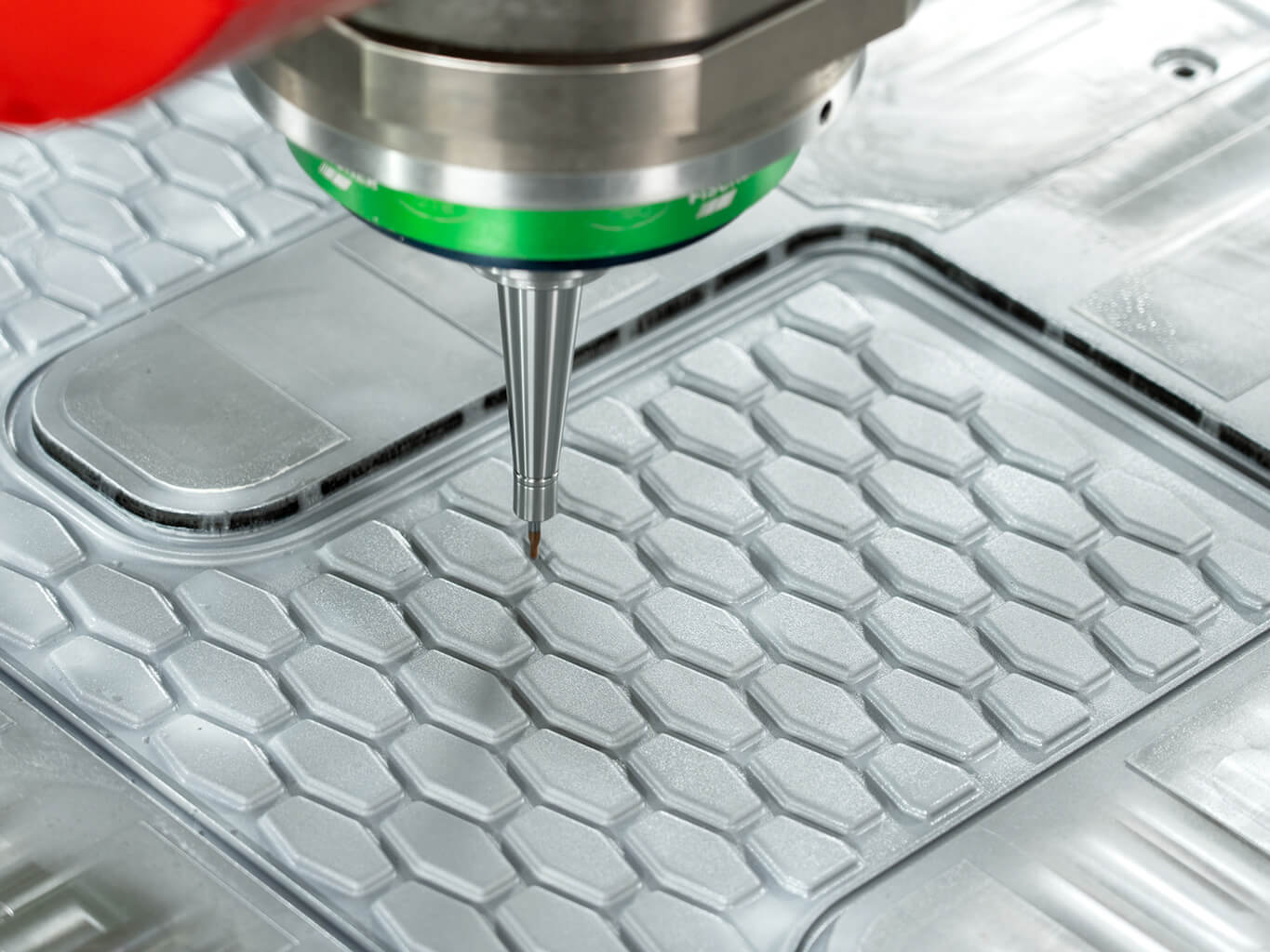
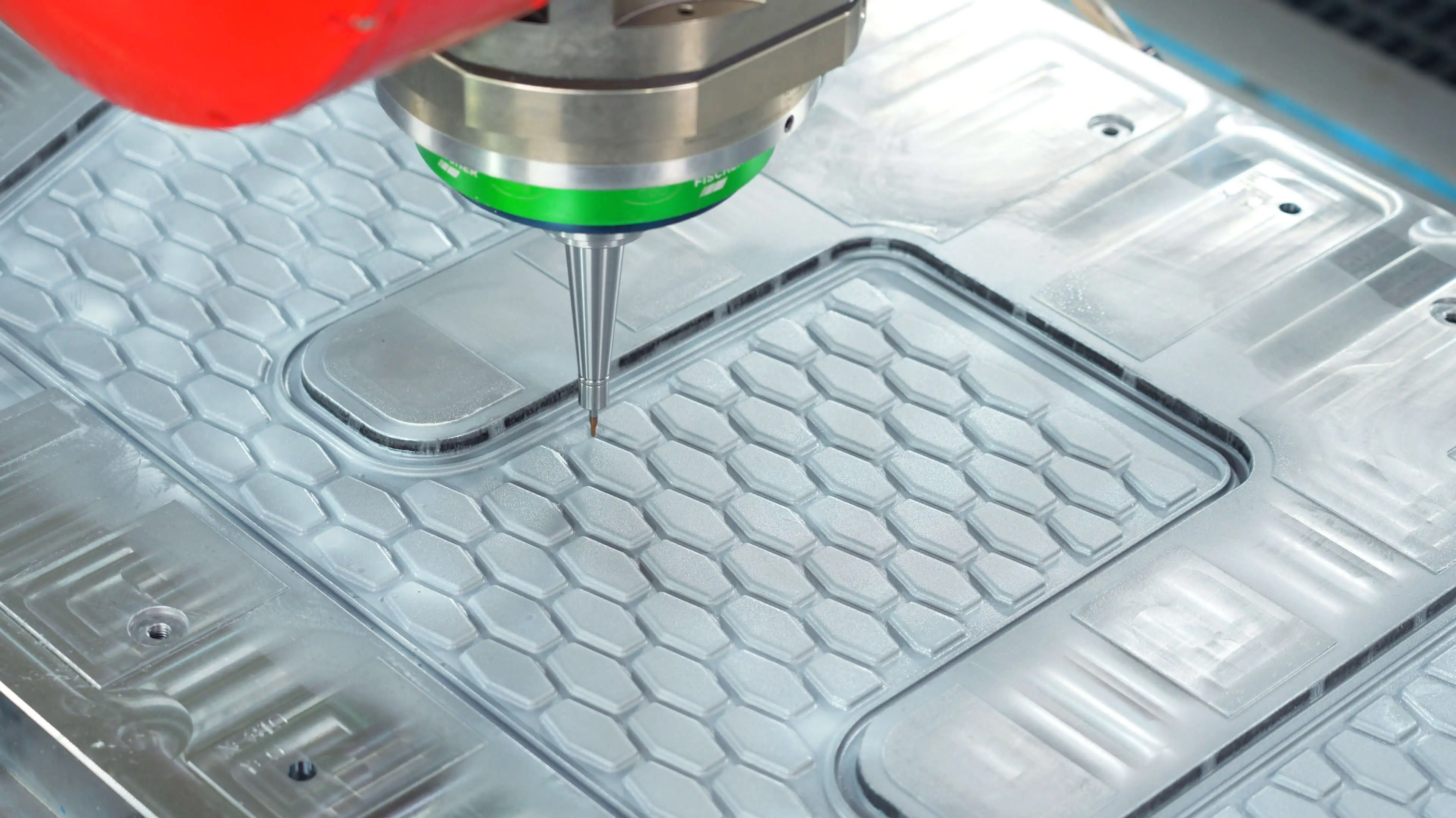
Mold cavity machining AMP high-speed CNC machining precise pockets and profiles into a steel mold component at our in-house tooling facility
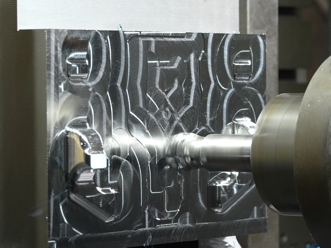
Mold cavity detail work AMP CNC machining detailed cavity features into a steel mold component, with all cutting done in-house
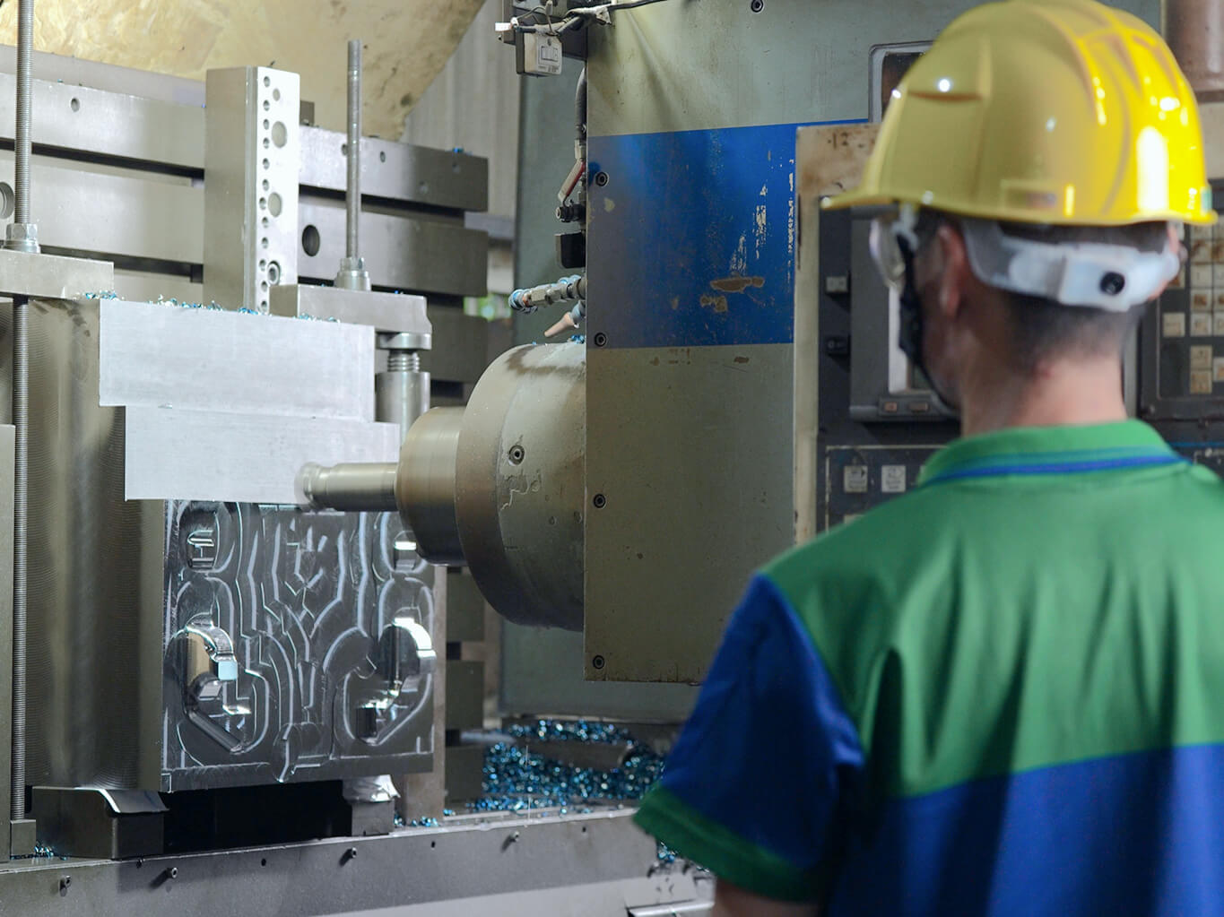
Operator overseeing mold base machining AMP toolmaker monitoring a large mold base during CNC machining, with steel chips visible from heavy cutting on in-house equipment
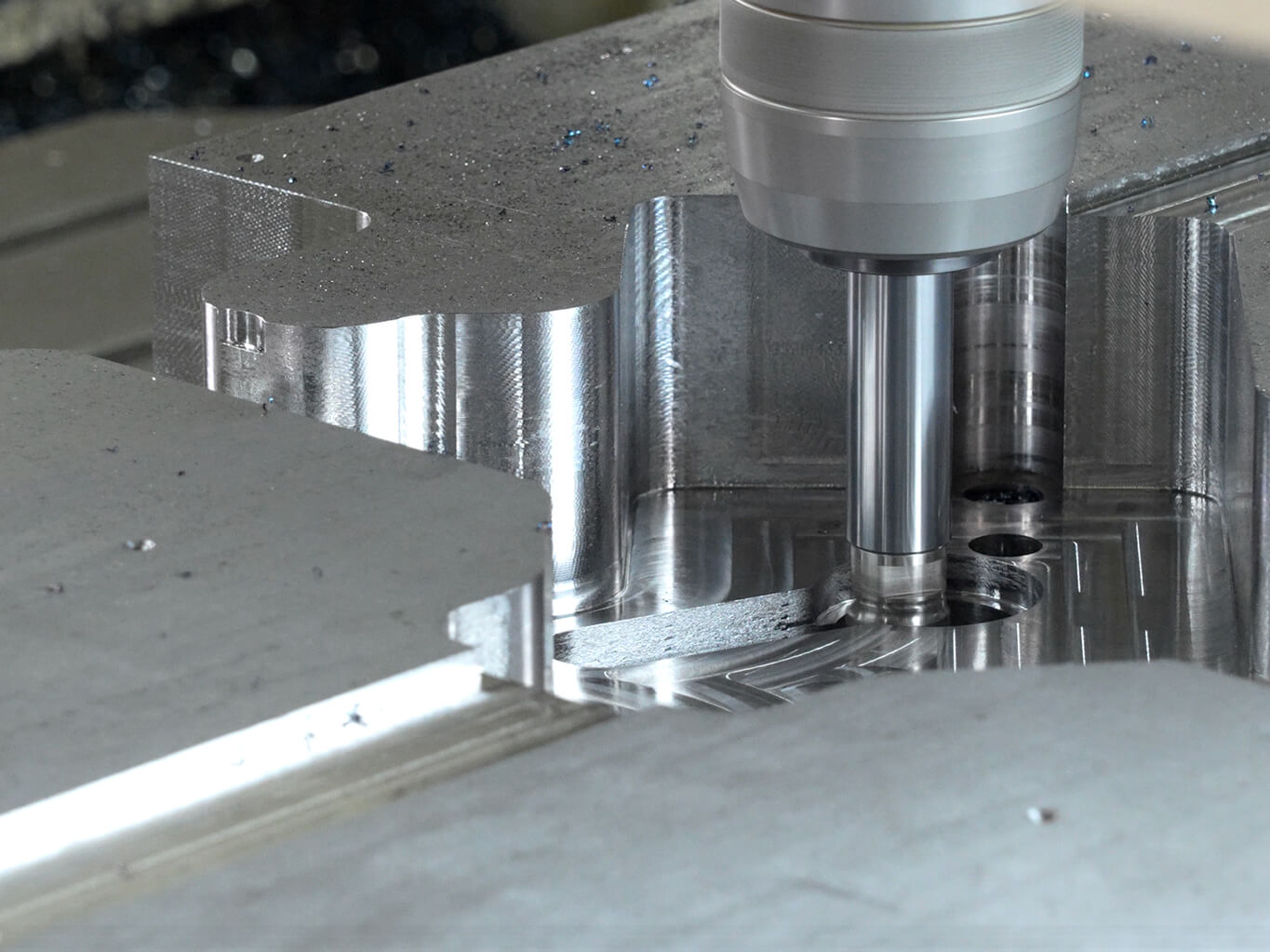
Mold component pocket machining AMP CNC machining precise pockets and profiles into a steel mold component using high-speed end milling
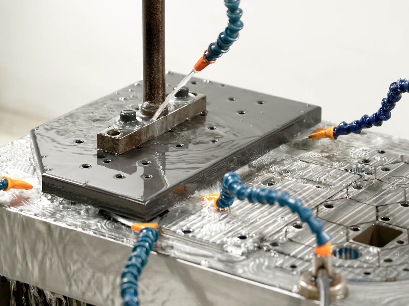
Sinker EDM machining AMP uses sinker EDM to machine fine details and complex shapes into hardened mold steel that conventional CNC cutting cannot reach
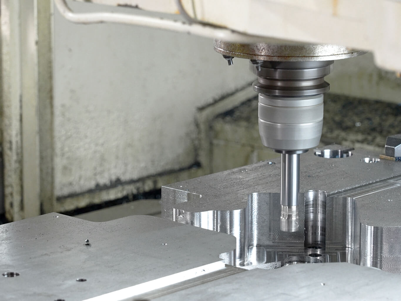
High-speed mold cavity cutting AMP high-speed CNC machining detailed cavity features into a steel mold component at our in-house tooling facility
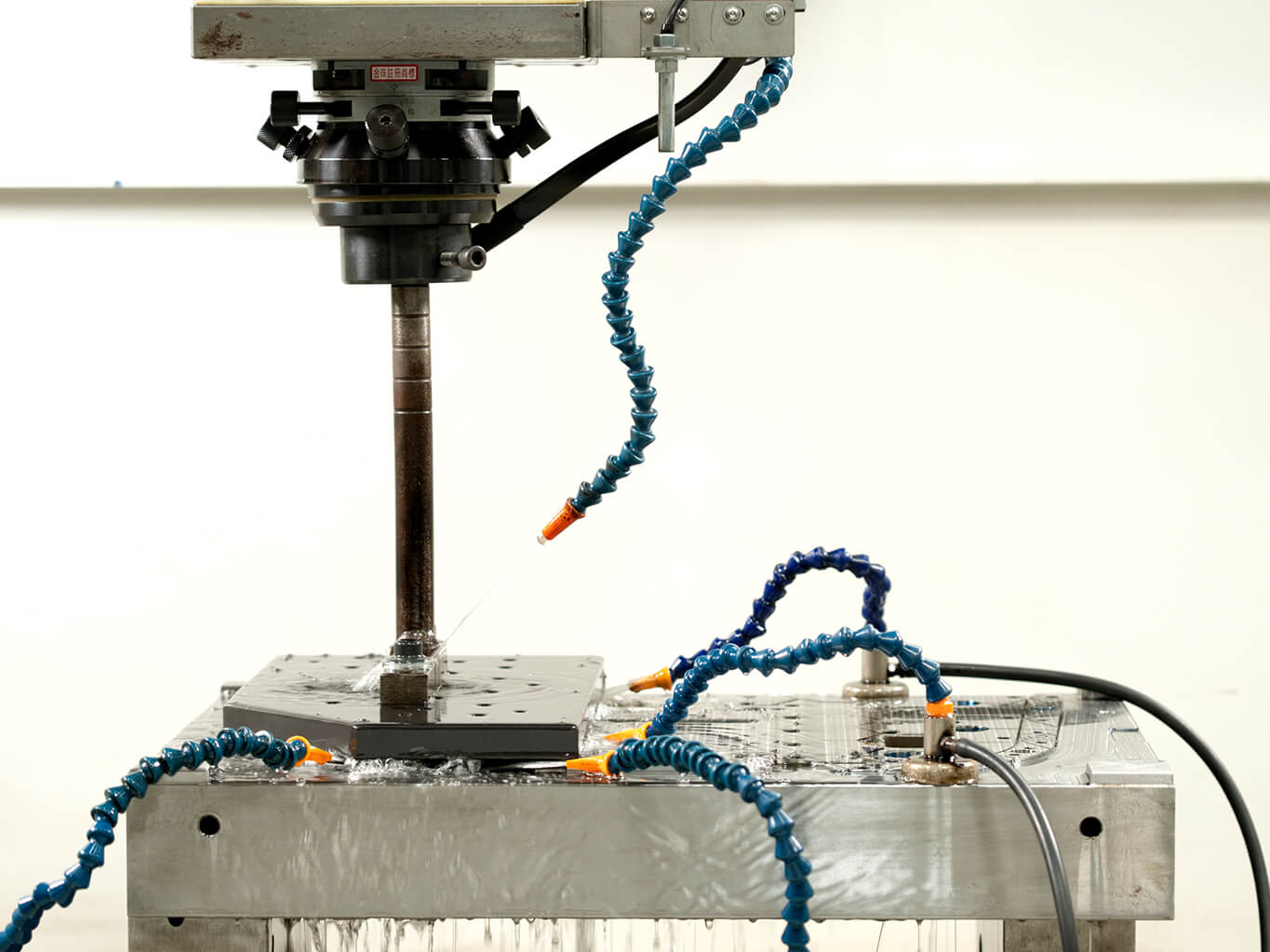
Sinker EDM on mold component AMP sinker EDM machining detailed features into a mold cavity insert with dielectric fluid lines positioned for flushing
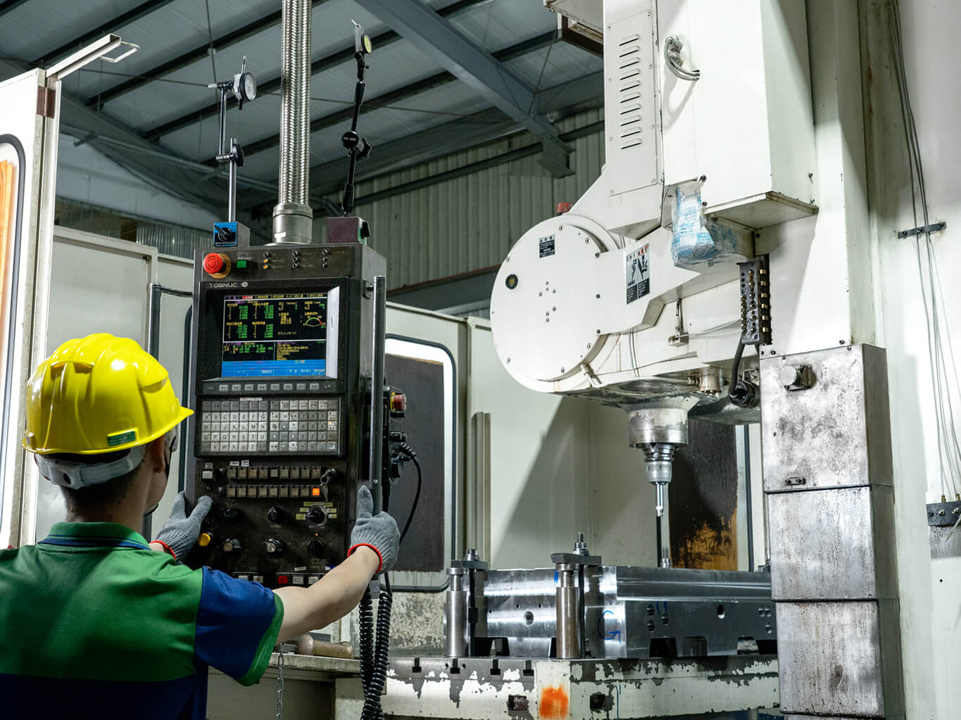
FANUC-controlled mold base machining AMP operator programming a FANUC-controlled CNC machine during mold base machining at our in-house tooling facility
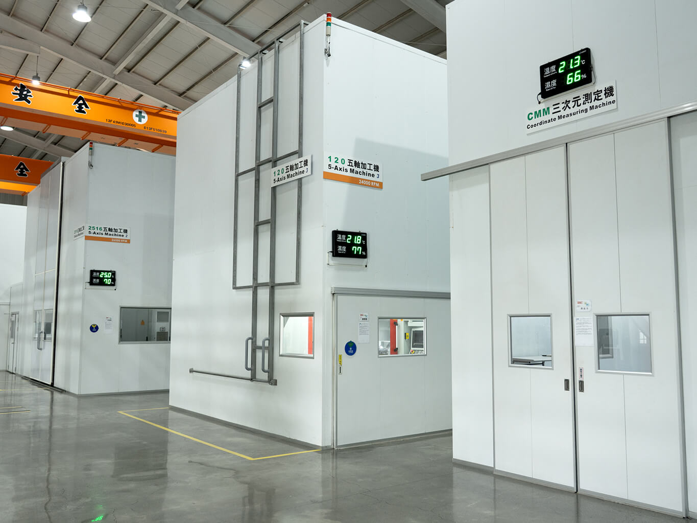
Climate-controlled 5-axis and CMM facility AMP houses its three 5-axis CNC machines and Coordinate Measuring Machine in separate climate-controlled rooms with live temperature and humidity displays for consistent machining accuracy
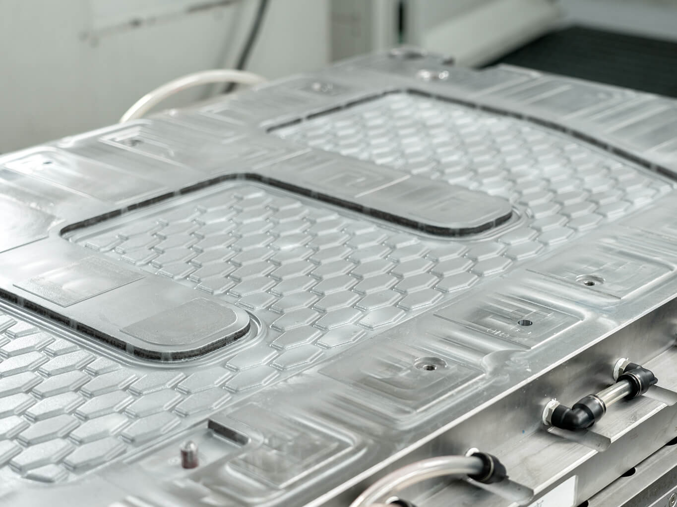
Completed floor mat mold AMP-machined automotive floor mat mold with textured tread pattern and cooling lines, ready for injection molding production
Get Answers From Our Experts
In-House Tooling FAQ
If your question is not listed here, please contact us and our team will be glad to assist you.
Both. Our largest machining center handles work up to 3,000 by 2,100 by 1,000mm, so we can cut large tool bases for parts like bumpers or floor mats in a single setup, while our smaller high-speed centers handle fine cavity detail on compact components. The eight-machine range means we are not forced to split a large tool across beds or turn away oversized work.
Yes. Three of our eight machining centers are 5-axis boring and milling machines. 5-axis lets us reach complex mold geometries and undercuts in fewer setups, which reduces repositioning error and holds better accuracy across large or contoured tool bodies.
Our centers run Heidenhain and Siemens controls from Germany and FANUC and Mitsubishi controls from Japan, on machines reaching spindle speeds of 26,000 RPM. These are the same control platforms used across the precision tooling industry, which matters for surface finish, repeatability, and the ability to run demanding cutting strategies on hardened steel.
Our high-speed centers and 5-axis machines are built for hard-milling and detailed steel work, which is what durable production tooling requires, including tooling for abrasive materials such as glass-fiber-reinforced compounds. Steel grade for a specific tool is matched at the design stage to your part, expected volume, and resin.
Every component is measured against the original 3D design before it moves to assembly. We use a Mitutoyo coordinate measuring machine for critical dimensions and a GOM ATOS 3D scanner that captures full-surface geometry down to 1 micron, so any deviation is found and corrected at the machining stage rather than after the mold is built.
A molder that buys tools from a separate shop manages a handoff every time a tool needs adjustment. Because we machine and verify tools in the same facility that molds your part, changes and corrections move directly between our machining floor and our injection lines, which shortens revisions and keeps one supplier responsible for the result.